- Home
- Products
- Solution
-
Support

-
- Let collaborators satisfaction

-
- Exceed customer expectations continue to provide products and services
-
About US

- To create the best social environment
-
- We realize that people peace, happiness, happy life for the vision
- Pearmain Mall
- Contact US

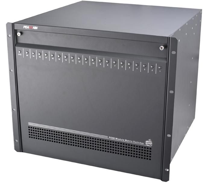
PE60 analog video matrix
PE60 matrix switcher is with modularization structure, can assemble according to requirement, which is an integrated audio & video matrix control/switch system of big CCTV surveillance system. Single unit can control or switch up to 256ch video inputs and 32ch video outputs, extension matrix can be 8224 inputs and 512 outputs. PE60 can have as many as 64 keyboard controllers and 2047 receiver/driver. LCD display and on-screen status display can indicate system working status. PE60 can control multiple front devices by PE5131 terminal receiver/driver or PE5135 code converter, including Speed dome (pan/tilt), lens, lighting and all kinds of alarm sensor (by PE5140 alarm interface), system has functions of alarm linkage, automatic and manual VCR control. PE60 contains one or multiple matrix switch bay, There are power module, communication module, VIM (video input/buffer module), VOM (video output and character superposed module) and relevant rear panel inside of matrix bay. All of PE60 systems is controlled by a internal process module--CPU board and one or multiple keyboard controller.
Product catalogSpecification Download fileOrder online
Integrated Menu Setup
PE60 matrix switcher is with integrated Menu Setup, including English operation interface, system setup functions, such as system jurisdiction, switch, alarm, etc, keyboard port , program port and built-in icon and 16-chracter display to make user can program or set by OSD menu.
Monitor with Status Display
While system running, it will display camera number under control, camera title, monitor number, time and date, “RUN”、“HOLD”, program switch--“PROM”, tour switch--“TOUR”, salvo switch---“SALVO”, alarm enable--“ENA”, alarm--“ARM” - on screen.
Video Switch
PE60 matrix switcher can switch any camera image or preset image to designated monitor, it with a a full cross-point matrix switcher, to configure as a cross-point switch of 16-2048 cameras to 8-128 monitors.
Individual Monitor Automatic Switch
Any camera image can be operator-defined on any monitor at any time, dwell time of each camera image is independently set, same camera image can display multiple times in a group of signals of auto switch.
Salvo Switch
System can switch simultaneously multiple camera images to multiple monitors, system can set 4 groups of salvo via salvo switch menu, every group can have up to 32 salvo, every salvo can have 16 monitors to switch, salvo switch can menu program setup.
Tour Switch
camera images can be tour randomly, system can pre-program and store 64 tour switch sequences, each sequence includes 64 camera images, every camera image dwell time is individually programmed, every camera signal can be a preset image, a tour can have same camera multiple times, multiple presets of a camera.
Group Switch
group switch should be on basis of existing salvo switch, each group salvo switch or auto switch on relevant monitor groups, There are up to 4 groups in a system.
Tour Switch Linkage
Calling tours according to system setup can bring to linkage action.
Camera images’ Jumping Over and Inserting
Camera images’ jumping over: to Jump over camera images, which doesn’t want to display when automatic switch on monitor.
Camera images’ inserting: to Insert camera images which haven’t displayed but want to display when automatic switch on monitor.
Automatic Alarm Switch
via alarm interface (PE5140 series), It can have 8-2048 alarm inputs (while extending), and 8-2048 alarm linkage outputs (while extending), it is P-bus control mode, once receiving alarm signal, system will switch alarm image automatically, run preset, auxiliary switch, video recorder, and it will output alarm status information to monitor, called image, dwell time, preset image, and auxiliary action time can be set by menu.
Alarm Control
Powerful alarm zone men setting, multiple alarm enable, disable, alarm management.
Mode 1: to display all system existed alarm images on monitor 1, display modes including orderly mode and fixed mode:
(1) Orderly mode: to display orderly multiple alarm images on monitor 1,in this mode, every alarm image will display ceaselessly until alarm is cleared, switch time of orderly mode can set by program, default switch time is 2 seconds.
(2) Fixed order: to display many alarm images in fixed order on monitor 1, in this mode, first alarm image will displayed on monitor 1 as alarm enabled, when second and more alarm enabled, they will be waited orderly, till first alarm image is cleared, then following alarm image will display.
Mode 2: to display all alarm images in progressive order on all monitors, fixed order only.
Fixed order: to display all alarm image in progressive order on all monitors, When alarm enabled, first alarm image will display on monitor 1, second alarm image will be displayed on monitor 2,….. NO.N alarm image will display on monitor N, once all monitors have displayed alarm images, following later alarm images will wait seriatim until previous alarm image is cleared.
Mode 3: to display some random alarm images on a random monitor.
Orderly mode: to display some random alarm images on a random monitor, in this mode, every alarm image will display ceaselessly until alarm is cleared, switch time of orderly mode can set by program, default time is 2 seconds.
Fixed order: to display some random alarm images on a random monitor, first alarm image will display on designated monitor when alarm enabled, alarm images will wait when second alarm image or more alarms enabled, they will display seriatim until previous alarm image is cleared.
Mode 4: Grouped display, all sensor to display all alarm image of same alarm zone on all monitors, corresponding relation of alarm zone and camera set by group menu, If alarm enabled in this zone, it will call and output alarm message on 8 monitors of this alarm group.
Orderly mode: To display each alarm image in same time on multiple monitors, switch time of orderly mode can set by program, default time is 2 seconds.
Fixed order: To display first alarm image on multiple monitors, it will display seriatim until previous alarm image is cleared.
Alarm Clearing
There are two alarm clear modes: Automatic and Manual, Both clear modes can make system exit alarm status and monitors return to previous status before alarming.
1. Automatic clear: (System clears alarm after alarm cut-off for 20 seconds)
This mode is done by alarm contactor automatic clear, once alarm contactor cut- off, alarm image will be cleared from monitor after 20 seconds delay, This mode can catch alarm of any time, once a alarm image has been cleared, next image will display on the monitor.
2. Manual clear: In this mode, each alarm image will be saved in relevant monitor and alarm will be cleared until monitors are visited by keyboard.
Video detection
It will detect video automatically, once video signal is abnormal or loss, it will inform control panel and display on monitor.
Audio Switch
It can switch 16--2048ch ( or more), To switch audio following by video synchronously or out of sync.
Alarm time delay Setup
Alarm time delay is delay time of system responding to signal when system receives alarm signal, this function can set by menu.
Operation permission setting
PE60S can set multiple operation permission according to practice, it include Super administrator, administrator, operation users.
System Partitioning Control
In order to improve safety and reliability, system have partitioning control function, to authorize different partition control to keyboard, monitors, and keyboard, as followings:
Monitor-to-camera partition: to set monitor to display camera images
Keyboard-to-camera partition: to set keyboard to control camera images Keyboard-to-monitor partition: to set keyboard to control monitor to display camera image.
Keyboard Control
System can have up to 64 keyboards and multimedia software, including main keyboard, multimedia software and sub keyboard.
Print Out Function
system can output real-time information by text format, to print out important data, such as “start time”, “turn-off time”, “alarm enable time”, “alarm removal time” and “alarm time”.
Memory Retention
All user-programmed data, which is stored in memory, is battery-backed for a minimum of 10 years, user parameters include all system parameters.
Multi-mode Control Bus
It is Multi-mode BUS, with 8 RS-485 ports, 1 RS-232 port,4 RS-422 ports and 1pcs 10/100M port.
|
Technology Specification |
|
|
Communication Mode |
serial (RS-485) RS-232 RS-422, P BUS |
|
P bus communication distance |
10km |
|
RS485/RS422 communication distance |
1300m |
|
RS232 communication distance |
15m |
|
Connection Mode |
STP (Shielded Twisted Pair) |
|
Bay content |
21 slot |
|
Video input module board |
16, every module can have 16ch video inputs, 1 16ch DB extension loop input. |
|
Video output module board |
4, every module can have 8ch video outputs, 3 DB extension loop input. |
|
CPU module board |
1 |
|
Bandwidth |
10MHz |
|
Video isolation degree |
-45dB |
|
Video S/N |
65 dB |
|
Differential Phase |
≤1.1ºC |
|
Differential Gain |
≤0.6% |
|
Insertion Gain |
≤0.1db |
|
Synchronous Nonlinear Distortion |
0.01 |
|
Brightness Nonlinear Distortion |
0.015 |
|
Inter-modulation Distortion |
0.005 |
|
Amplitude Frequency Characteristic |
1.5db |
|
Waveform Distortion in a Short Time |
0.035 |
|
Cluster Frequency Delay Characteristics |
6ns |
|
Brightness/Color Time Delay Offset |
2.5ns |
|
Brightness/Color Time Delay Gain |
0.08 |
|
Video Input Signal |
1Vp-p /75Ω |
|
Video Output Signal |
1Vp-p /75Ω |
|
Audio Input Signal |
1Vp-p |
|
Audio Output Signal |
1Vp-p |
|
Maximum Inputs (can be controlled) |
5012 |
|
Maximum Receiver/drivers (can be controlled) |
2047 |
|
Maximum allocated keyboard |
64 |
|
Memory Retention in Power-off |
10 years |
|
Working temperature |
-10℃~ +55℃ |
|
Working Voltage |
AC 220V ±10% 50/60 Hz |
|
Main Engine Power |
70W |
|
Main Engine Weight |
15 pounds |
|
Main Engine Size |
432(width)×406(height)×372(depth)mm |
|
Installation Mode |
desktop or 19-inch standard rack |
Relevant information of PE60 analog video matrix

You are not logged, Please log in,or registration for business users
Please log in,or registration for business users Related Solutions
No relevant solutions